

-
Integral Thickness Measuring
One of the most pressing problems of nondestructive testing (NDT) is detection of corrosion damage of the object and determination of its extent. Generally, values of residual wall thickness and areas of corrosion damage are used as a quantitative characteristic of the degree of damage. To determine these parameters, ultrasonic thickness gauges are commonly used which allow for making local measurements of the wall thickness. The disadvantages of this method are the high labor content of testing of large-area objects, the necessity to remove insulation on the whole tested area, the impossibility to measure thickness of the object areas to which there is no physical access.
These disadvantages lead to that the thickness is usually measured on a small part of area of the tested object as a result of which the degree of corrosion damage is determined with low accuracy; there is a probability of missing a corrosion defect, the degree of subjectivity of testing increases, and, in addition, the object parts of large area remain non tested at all. It should be also mentioned that arrangement of monitoring of the large-area objects by the methods of ultrasonic thickness measuring is a complicated problem.
Thus, the urgent problem is development of the method that permits to carry out an integral measuring of thickness, i.e. to receive data on the wall thickness between the sensors mounted on the object some distance apart. To solve the assigned task by the acoustic methods, it is necessary to transmit the signal through few meters of the object wall. This requires changing frequency range from the region of above 1 MHz that is typical for the conventional ultrasonic thickness gauges to the range from 10 kHz to 500 kHz that is typical for AE testing.
INTERUNIS-IT has developed the method of integral thickness measuring and monitoring, which is based on the phenomenon of dependence of group velocity of Lamb waves on the product of frequency and wall thickness, and realizable on the basis of standard AE systems and AE sensors.
The work scheme is as follows. On the object at a distance of several meters or tens of meters apart two AE sensors are placed (Fig. 1). They are used as a transmitter and a receiver of the acoustic signals. At the transmitter an electrical delta-pulse is fed with the result that this AE sensor radiates a wideband impulse. The signal propagates along the wall of the object in the form of a combination of Lamb waves and is registered by a second AE sensor. The spectrogram of the received signal is calculated. Its processing makes it possible to determine with high accuracy the arrival times t(f) of the various frequency components of the Lamb waves, which in the following manner depend on the plot of the thickness values h(x) at the section between the AE sensors:

Analysis of the frequency dependence of the arrival times of Lamb waves enables to get information about the thickness values at the segment between sensors. Here, vi is a group velocity of i-th mode of Lamb wave, tRAD is a time point of radiation, L is a distance between sensors. The process of processing the spectrogram and determining the wall thickness can be carried out either manually or automatically. Operating frequencies are of the order of 2000 kHz ∙ mm / h, where h is the characteristic wall thickness.
Several series of experiments were carried out to test the work of the method. It was revealed that:
1. The monitored zone is an area elongated along a segment connecting the AE sensor, an area having a width of no more than 2-6% of the distance between the sensors. Welds do not affect the measurement process.
2. Tests on decommissioned objects showed that the method is at least operable in a thickness range of 4-40 mm, with a pipe diameter of 500-1220 mm. At the same time, the maximum distance between 2 AE sensors is limited by attenuation of the acoustic signal and for pipes in good condition reaches up to 12 m in the presence of insulation and at least up to 56 m on pipelines with insulation removed. On objects with a constant wall thickness, the accuracy of determining the thickness reaches 1%.
3. In working conditions on the territory of petrochemical plants, the method is operable at least on pipes without insulation with a diameter of 221-431 mm at distances from 1 to 7 m. The error in determining the thickness is about 10%. An important condition is the absence of liquid in the tested object.
Since the method is based on the analysis of Lamb waves propagating through the entire thickness of the object wall from one AE sensor to another and the signals reflected from the defects are not used in it, the following limitations and peculiarities exist:
1. Distinguishing between local and general thinning or localization of thinning is possible only by correlating the results of several measurements with different positions of the AE sensor.
2. It is not possible to detect pitting and other local lesions smaller than the length of the acoustic wave, in this case about 15 mm.
3. The method does not distinguish between external and internal corrosion.
Emitter and receivers arrangement on the testing object and the arithmetic mean thicknesses values between them
Spectrograms of signals corresponding to a wall thickness 13 mm and 17 mm
-
Pipeline pigs detection
Today, the main fields of NDT use include pipeline testing. Most of such objects have a significant length in the axial direction, as a result of which the hand testing of the entire object is unpractical both as regards time and financial costs. On this basis, the pipeline pig has become very widespread in this industry. One of the problems with the pipeline pig use is the lack of information about the flaw detector location during testing. As a result, in the event if the flaw detector stops, that may occur for a number of reasons, its position will be unknown. Therefore, the actual problem for the in-line testing is monitoring of the flaw detector movement.
The specialists of "INTERUNIS-IT" conducted a number of experiments using low-frequency sensors of AE, which allowed recording the movement of the pig at distances up to 20 km. A clear tendency has been found to reduce the amplitudes of the AE signals as the flaw detector is removed from the AE sensor. A more detailed examination makes it possible to detect periodic strokes of the flaw detector using welded seams, allowing to determine the speed of the flaw detector. Work is under way to determine the coordinates of the flaw detector with accuracy to the weld.
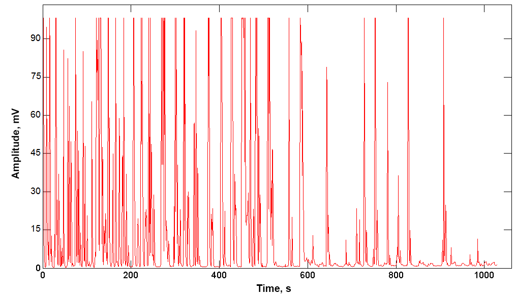
Impulses from the impact of a flaw detector and welds
-
AE testing in the operating mode
Traditionally, AE testing is carried out for objects decommissioned. This requirement is related both to the effect of the Kaiser, leading to the need to exceed the test load over the working load, and with an increased level of noise during the operation of the facility. However, the AE testing in operation mode is acceptable provided the data acquisition period of the AE data is longer and a specialized methodology is developed.
Since the diagnostics depends on the features of the technological process and the operational loading of the equipment, the development of a separate AE testing technique in operation is required for each type of tested facility. During development, it is necessary to conduct a detailed preliminary diagnostic testing of the facility, including an assessment of the level and spectrum of acoustic noise in order to maximize the signal-to-noise ratio. It is also necessary to analyze the change in operating parameters: temperature and operating pressure for static equipment, rotation mode for dynamic equipment, and based on it to build an algorithm for interpreting AE data.
INTERUNIS-IT carried out research to assess the possibility of organizing continuous monitoring AE without decommissioning the following facilities: load-bearing elements of the walking dragline excavator, a high-temperature process pipeline, a 7-span automotive bridge across the river, and roller bearings of a rotating furnace. For each of the objects, the optimal operating frequency range, the threshold level and the distance between the sensors were determined, and a data analysis technique was developed to identify useful signals against a background of high noise.
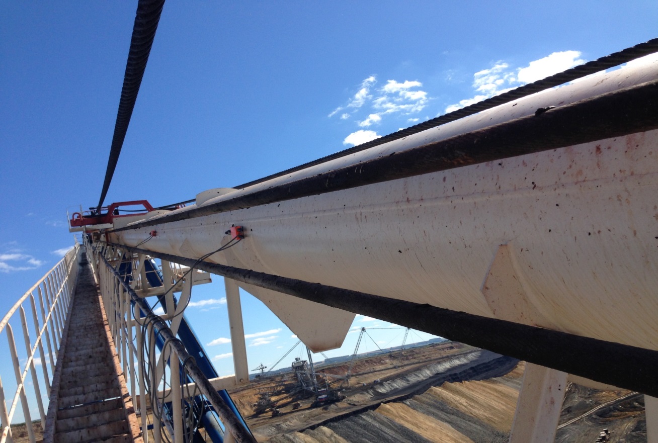
For AE diagnostics of booms and struts of a walking dragline excavator with a boom length of 90 m and a bucket capacity of 20 m3 without a decommissioning, a 30-channel AE system was used. When using the frequency range of 150-500 kHz and a threshold of 50 dB, the AE activity acquired a cyclic character synchronized with the excavator operation mode. Recommended from the measurement of the attenuation of the distance between the sensors were 4.5 to 9 m. The AE data acquisition was carried out for 2 days. On the lower boom belt there were no sources of AE. On the column and the upper boom belt, several AE sources were identified, which turned out to be the noise of the winch. Six sources of AE were revealed on the left and right strands, two of them were classified as 20 and 30 mm cracks according to the results of ultrasonic testing.
At the AE testing of the high-temperature process pipeline the most suitable was the use of the frequency range 100-500 kHz and the threshold in the region of 40-55 dB. it was found that the noise level increases significantly with a temperature change rate of more than 1°C / min. It is revealed that the attenuation coefficient of the AE signal significantly increases with the accumulation of deposits in the internal volume of the pipeline. Using the AE method, leakage through the flange joints was detected long before it, hidden under the layer of thermal insulation, became visually noticeable.
Work was carried out on the comprehensive diagnosis of the 7-meter-long automobile 7-span metal bridge across the river. The foundations for reinforced concrete pillars are piled. The specially developed monitoring version of the AE-system included not only 33 AE sensors installed in the most potentially dangerous places, but also vibration sensors, strain gauges, temperature sensors, inclinometers, crack opening sensors, video cameras, and a weather station and a wireless microwave relay unit. In the analysis of AE data, a high level of noise caused by vibration and knocking during vehicles and gusts was detected. The optimal frequency range (60-200 kHz) is selected, the need for fixing loose structural elements is shown. It is revealed that on the linear part of the bridge the optimal distance between AE sensors is about 6 m. A multistage noise filtering algorithm including selection based on AE parameters is proposed and the dependence of the defect detection probability on the distance between AE sensors is determined.
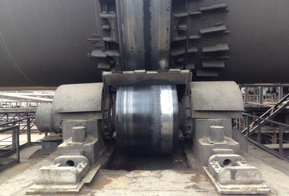
At the alumina plant in the shops of sintering and calcination, 15 supporting blocks of rotary kilns with different service lives were examined. It is revealed that external noise does not exceed 32 dB, except for strictly periodic signals associated with scuffing and roughness on the surface of the roller or bandage of the furnace. It was revealed that for monitoring it is required to install 3 AE sensors on each of the 2 bearing housings, and also to install 1 sensor on opposite ends, after removing the end caps of the shaft. According to the AE data, such defects as fatigue cracks in the junction transitions, wear of the shaft surface during frictional contact, crack of the inner ring of the bearing and brinelling, as well as violation of the lubrication regime were identified.
Thus, it is shown that the task of AE testing for various objects without putting them out of operation, despite its complexity, is completely solvable. The application, in addition to other methods of NDT, AE diagnostics, which possesses such unique qualities as high sensitivity and high diagnostic performance, allows to significantly reduce the risk of equipment failure without significant increase in the costs of monitoring operations.
-
Low-frequency acoustic emission
Today, there is an extensive network of trunk pipelines on the territory of Russia, covering 35% of the country's territory, crossing roads and railways, rivers and forests, sometimes passing in close proximity to populated areas. Since transported environments in most cases have a fire and explosion hazard, great importance is attached to issues of reliability and safety.
One of the methods of non-destructive testing used to detect defects in the operation of main pipelines is the acoustic emission method (AE), which has a high sensitivity to the most dangerous (developing) defects, provides an integrated assessment of the technical condition of extended sections of pipelines and takes into account the dynamics of defects development assessment of their degree of danger.
Despite the high efficiency of the AE method and modern AE equipment, which allow to test up to 8 km of the pipeline in one measurement cycle, one of the main problems preventing the wider application of this method on pipelines of underground laying is the need to making pits for mounting piezoacoustic sensors on the pipe surface at a distance of 12-70 m from each other. This requirement arises due to the fact that at long distances between pits acoustic signals from defects, that may be present on the monitored object, can decay and not reach the closest sensors, usually operating at frequencies of 30-500 kHz.
Since attenuation of acoustic signals is usually proportional to the frequency, the main way to increase the distance between the pits to 100 meters or more is to lower the operating frequencies to 0.1-30 kHz. However, in the transition to the region of low operating frequencies, in addition to the amplitudes of the useful signals, the noise amplitudes also increase. Thus, the solution of the problem posed requires the development of a technique for efficient algorithms and filters that can confidently detect a useful signal in the presence of strong jamming or unsteady process noise with a different nature and a priori unknown properties, incl. at a signal to noise ratio of less than one.
INTERUNIS-IT conducts research in this area. Research includes a zero-threshold continuous data acquisition on pipelines with the help of AE sensors and vibration sensors remoted from each other at distances up to 200 m, operating at frequencies from 0.2 to 60 kHz. To remove noise, specialized filtering methods are developed and applied, automatically adapted to the characteristics of background noise. To locate low-amplitude and remote sources of AE, special threshold-free methods for determining the arrival time of the signal are developed, in addition, correlation methods of location are used. To theoretically assess the capabilities of the method, analyze the propagation of the vibration modes and test the developed location methods, the AE signal propagation modeling through the pipeline by the finite element method is used.
One of the most pressing problems of nondestructive testing (NDT) is detection of corrosion damage of the object and determination of its extent. Generally, values of residual wall thickness and areas of corrosion damage are used as a quantitative characteristic of the degree of damage. To determine these parameters, ultrasonic thickness gauges are commonly used which allow for making local measurements of the wall thickness. The disadvantages of this method are the high labor content of testing of large-area objects, the necessity to remove insulation on the whole tested area, the impossibility to measure thickness of the object areas to which there is no physical access.
These disadvantages lead to that the thickness is usually measured on a small part of area of the tested object as a result of which the degree of corrosion damage is determined with low accuracy; there is a probability of missing a corrosion defect, the degree of subjectivity of testing increases, and, in addition, the object parts of large area remain non tested at all. It should be also mentioned that arrangement of monitoring of the large-area objects by the methods of ultrasonic thickness measuring is a complicated problem.
Thus, the urgent problem is development of the method that permits to carry out an integral measuring of thickness, i.e. to receive data on the wall thickness between the sensors mounted on the object some distance apart. To solve the assigned task by the acoustic methods, it is necessary to transmit the signal through few meters of the object wall. This requires changing frequency range from the region of above 1 MHz that is typical for the conventional ultrasonic thickness gauges to the range from 10 kHz to 500 kHz that is typical for AE testing.
INTERUNIS-IT has developed the method of integral thickness measuring and monitoring, which is based on the phenomenon of dependence of group velocity of Lamb waves on the product of frequency and wall thickness, and realizable on the basis of standard AE systems and AE sensors.
The work scheme is as follows. On the object at a distance of several meters or tens of meters apart two AE sensors are placed (Fig. 1). They are used as a transmitter and a receiver of the acoustic signals. At the transmitter an electrical delta-pulse is fed with the result that this AE sensor radiates a wideband impulse. The signal propagates along the wall of the object in the form of a combination of Lamb waves and is registered by a second AE sensor. The spectrogram of the received signal is calculated. Its processing makes it possible to determine with high accuracy the arrival times t(f) of the various frequency components of the Lamb waves, which in the following manner depend on the plot of the thickness values h(x) at the section between the AE sensors:
Analysis of the frequency dependence of the arrival times of Lamb waves enables to get information about the thickness values at the segment between sensors. Here, vi is a group velocity of i-th mode of Lamb wave, tRAD is a time point of radiation, L is a distance between sensors. The process of processing the spectrogram and determining the wall thickness can be carried out either manually or automatically. Operating frequencies are of the order of 2000 kHz ∙ mm / h, where h is the characteristic wall thickness.
Several series of experiments were carried out to test the work of the method. It was revealed that:
1. The monitored zone is an area elongated along a segment connecting the AE sensor, an area having a width of no more than 2-6% of the distance between the sensors. Welds do not affect the measurement process.
2. Tests on decommissioned objects showed that the method is at least operable in a thickness range of 4-40 mm, with a pipe diameter of 500-1220 mm. At the same time, the maximum distance between 2 AE sensors is limited by attenuation of the acoustic signal and for pipes in good condition reaches up to 12 m in the presence of insulation and at least up to 56 m on pipelines with insulation removed. On objects with a constant wall thickness, the accuracy of determining the thickness reaches 1%.
3. In working conditions on the territory of petrochemical plants, the method is operable at least on pipes without insulation with a diameter of 221-431 mm at distances from 1 to 7 m. The error in determining the thickness is about 10%. An important condition is the absence of liquid in the tested object.
Since the method is based on the analysis of Lamb waves propagating through the entire thickness of the object wall from one AE sensor to another and the signals reflected from the defects are not used in it, the following limitations and peculiarities exist:
1. Distinguishing between local and general thinning or localization of thinning is possible only by correlating the results of several measurements with different positions of the AE sensor.
2. It is not possible to detect pitting and other local lesions smaller than the length of the acoustic wave, in this case about 15 mm.
3. The method does not distinguish between external and internal corrosion.
Emitter and receivers arrangement on the testing object and the arithmetic mean thicknesses values between them
Spectrograms of signals corresponding to a wall thickness 13 mm and 17 mm
Today, the main fields of NDT use include pipeline testing. Most of such objects have a significant length in the axial direction, as a result of which the hand testing of the entire object is unpractical both as regards time and financial costs. On this basis, the pipeline pig has become very widespread in this industry. One of the problems with the pipeline pig use is the lack of information about the flaw detector location during testing. As a result, in the event if the flaw detector stops, that may occur for a number of reasons, its position will be unknown. Therefore, the actual problem for the in-line testing is monitoring of the flaw detector movement.
The specialists of "INTERUNIS-IT" conducted a number of experiments using low-frequency sensors of AE, which allowed recording the movement of the pig at distances up to 20 km. A clear tendency has been found to reduce the amplitudes of the AE signals as the flaw detector is removed from the AE sensor. A more detailed examination makes it possible to detect periodic strokes of the flaw detector using welded seams, allowing to determine the speed of the flaw detector. Work is under way to determine the coordinates of the flaw detector with accuracy to the weld.
Impulses from the impact of a flaw detector and welds
Traditionally, AE testing is carried out for objects decommissioned. This requirement is related both to the effect of the Kaiser, leading to the need to exceed the test load over the working load, and with an increased level of noise during the operation of the facility. However, the AE testing in operation mode is acceptable provided the data acquisition period of the AE data is longer and a specialized methodology is developed.
Since the diagnostics depends on the features of the technological process and the operational loading of the equipment, the development of a separate AE testing technique in operation is required for each type of tested facility. During development, it is necessary to conduct a detailed preliminary diagnostic testing of the facility, including an assessment of the level and spectrum of acoustic noise in order to maximize the signal-to-noise ratio. It is also necessary to analyze the change in operating parameters: temperature and operating pressure for static equipment, rotation mode for dynamic equipment, and based on it to build an algorithm for interpreting AE data.
INTERUNIS-IT carried out research to assess the possibility of organizing continuous monitoring AE without decommissioning the following facilities: load-bearing elements of the walking dragline excavator, a high-temperature process pipeline, a 7-span automotive bridge across the river, and roller bearings of a rotating furnace. For each of the objects, the optimal operating frequency range, the threshold level and the distance between the sensors were determined, and a data analysis technique was developed to identify useful signals against a background of high noise.
For AE diagnostics of booms and struts of a walking dragline excavator with a boom length of 90 m and a bucket capacity of 20 m3 without a decommissioning, a 30-channel AE system was used. When using the frequency range of 150-500 kHz and a threshold of 50 dB, the AE activity acquired a cyclic character synchronized with the excavator operation mode. Recommended from the measurement of the attenuation of the distance between the sensors were 4.5 to 9 m. The AE data acquisition was carried out for 2 days. On the lower boom belt there were no sources of AE. On the column and the upper boom belt, several AE sources were identified, which turned out to be the noise of the winch. Six sources of AE were revealed on the left and right strands, two of them were classified as 20 and 30 mm cracks according to the results of ultrasonic testing.
At the AE testing of the high-temperature process pipeline the most suitable was the use of the frequency range 100-500 kHz and the threshold in the region of 40-55 dB. it was found that the noise level increases significantly with a temperature change rate of more than 1°C / min. It is revealed that the attenuation coefficient of the AE signal significantly increases with the accumulation of deposits in the internal volume of the pipeline. Using the AE method, leakage through the flange joints was detected long before it, hidden under the layer of thermal insulation, became visually noticeable.
Work was carried out on the comprehensive diagnosis of the 7-meter-long automobile 7-span metal bridge across the river. The foundations for reinforced concrete pillars are piled. The specially developed monitoring version of the AE-system included not only 33 AE sensors installed in the most potentially dangerous places, but also vibration sensors, strain gauges, temperature sensors, inclinometers, crack opening sensors, video cameras, and a weather station and a wireless microwave relay unit. In the analysis of AE data, a high level of noise caused by vibration and knocking during vehicles and gusts was detected. The optimal frequency range (60-200 kHz) is selected, the need for fixing loose structural elements is shown. It is revealed that on the linear part of the bridge the optimal distance between AE sensors is about 6 m. A multistage noise filtering algorithm including selection based on AE parameters is proposed and the dependence of the defect detection probability on the distance between AE sensors is determined.
At the alumina plant in the shops of sintering and calcination, 15 supporting blocks of rotary kilns with different service lives were examined. It is revealed that external noise does not exceed 32 dB, except for strictly periodic signals associated with scuffing and roughness on the surface of the roller or bandage of the furnace. It was revealed that for monitoring it is required to install 3 AE sensors on each of the 2 bearing housings, and also to install 1 sensor on opposite ends, after removing the end caps of the shaft. According to the AE data, such defects as fatigue cracks in the junction transitions, wear of the shaft surface during frictional contact, crack of the inner ring of the bearing and brinelling, as well as violation of the lubrication regime were identified.
Thus, it is shown that the task of AE testing for various objects without putting them out of operation, despite its complexity, is completely solvable. The application, in addition to other methods of NDT, AE diagnostics, which possesses such unique qualities as high sensitivity and high diagnostic performance, allows to significantly reduce the risk of equipment failure without significant increase in the costs of monitoring operations.
Today, there is an extensive network of trunk pipelines on the territory of Russia, covering 35% of the country's territory, crossing roads and railways, rivers and forests, sometimes passing in close proximity to populated areas. Since transported environments in most cases have a fire and explosion hazard, great importance is attached to issues of reliability and safety.
One of the methods of non-destructive testing used to detect defects in the operation of main pipelines is the acoustic emission method (AE), which has a high sensitivity to the most dangerous (developing) defects, provides an integrated assessment of the technical condition of extended sections of pipelines and takes into account the dynamics of defects development assessment of their degree of danger.
Despite the high efficiency of the AE method and modern AE equipment, which allow to test up to 8 km of the pipeline in one measurement cycle, one of the main problems preventing the wider application of this method on pipelines of underground laying is the need to making pits for mounting piezoacoustic sensors on the pipe surface at a distance of 12-70 m from each other. This requirement arises due to the fact that at long distances between pits acoustic signals from defects, that may be present on the monitored object, can decay and not reach the closest sensors, usually operating at frequencies of 30-500 kHz.
Since attenuation of acoustic signals is usually proportional to the frequency, the main way to increase the distance between the pits to 100 meters or more is to lower the operating frequencies to 0.1-30 kHz. However, in the transition to the region of low operating frequencies, in addition to the amplitudes of the useful signals, the noise amplitudes also increase. Thus, the solution of the problem posed requires the development of a technique for efficient algorithms and filters that can confidently detect a useful signal in the presence of strong jamming or unsteady process noise with a different nature and a priori unknown properties, incl. at a signal to noise ratio of less than one.
INTERUNIS-IT conducts research in this area. Research includes a zero-threshold continuous data acquisition on pipelines with the help of AE sensors and vibration sensors remoted from each other at distances up to 200 m, operating at frequencies from 0.2 to 60 kHz. To remove noise, specialized filtering methods are developed and applied, automatically adapted to the characteristics of background noise. To locate low-amplitude and remote sources of AE, special threshold-free methods for determining the arrival time of the signal are developed, in addition, correlation methods of location are used. To theoretically assess the capabilities of the method, analyze the propagation of the vibration modes and test the developed location methods, the AE signal propagation modeling through the pipeline by the finite element method is used.